I2C Interfacing
Connecting a device to another device using I2C is a common practice. This chapter introduces the basics.
About I2C
The Inter-Integrated Circuit (I2C) protocol is a protocol intended to allow multiple slave devices to communicate with one or more master chips. I2C is a two signal wire bus protocol.
Why I2C? Because
- Its a common standard
- Easy to use
- Wide support
- Its "fast" for low-speed devices (100kbit - 400kbit)
- Bus (multiple devices can be connected)
- Each device connected to the bus is software-addressable by a unique address
- Only 2 communication lines required (SDA and SCL)
- The SCL and SDA lines are connected to all devices on the I2C bus
- SCL is the clock line.
- It is used to synchronize all data transfers over the I2C bus.
- No strict baud rate requirements like for instance with RS232, the master generates a bus clock.
- SDA is the data line.
- There does need to be a third wire which is the ground
Both SCL and SDA lines are "open drain" drivers. What this means is that the chip can drive its output low, but it cannot drive it high. For the line to be able to go high you must provide pull-up resistors to Vcc. There should be a resistor from the SCL line to Vcc and another from the SDA line to Vcc. You only need one set of pull-up resistors for the whole I2C bus, not for each device. Vcc depends on the devices used.
The devices on the I2C bus are either masters or slaves. The master is always the device that drives the SCL clock line. The slaves are the devices that respond to the master. There can be, and usually are, multiple slaves on the I2C bus, however there is normally only one master. It is possible to have multiple masters, but it is unusual. A slave cannot initiate a data transfer over the I2C bus, only a master can do that. Both master and slave can transfer data over the I2C bus, but that transfer is always controlled by the master.
Connecting a Raspberry Pi 3 to an I2C device
When connecting external devices to the Raspberry Pi, voltage levels should always be checked. The Raspberry Pi runs at 3.3V and is not 5V tolerant.
Normally I2C requires you to add a pull-up resistor to each line (SDA and SCL). However in the case of a Raspberry Pi 3 you will not need to add these. This because the Raspberry Pi 3 already has pull-ups of 1k8 on each i2c line.
HINT - Enabling i2c on the Raspberry Pi
Make sure to enable the i2c bus on the Raspberry Pi. This can be achieved using the
raspi-configtool by selectingInterface Options => I2C => Enable. You may need to restart the device.
I2c-tools
Before starting with the development of an actual application, its always best to first check if there is connectivity with the hardware. A handy tool at our disposal is i2cdetect, which can scan the i2c bus for devices. It is part of a package called i2c-tools. This whole package is very useful for debugging and testing.
Install the tools using the following commands:
sudo apt update
sudo apt install i2c-tools
2
From now on the i2cdetect tool can be used to scan the i2c bus and detect connected slave devices. First check the directory /dev for available i2c busses
cd /dev
ls i2c-*
2
Look for i2c-x where x is a number
By usingi2cdetect -r <x> and replacing <x> with the number of the actual device bus, the bus can be scanned. For example:
i2cdetect -r 1
You should get output similar to the one shown below if nothing is externally connected.
WARNING! This program can confuse your I2C bus, cause data loss and worse!
I will probe file /dev/i2c-1 using read byte commands.
I will probe address range 0x03-0x77.
Continue? [Y/n]
     0  1  2  3  4  5  6  7  8  9  a  b  c  d  e  f
00:          -- -- -- -- -- -- -- -- -- -- -- -- --
10: -- -- -- -- -- -- -- -- -- -- -- -- -- -- -- --
20: -- -- -- -- -- -- -- -- -- -- -- -- -- -- -- --
30: -- -- -- -- -- -- -- -- -- -- -- -- -- -- -- --
40: -- -- -- -- -- -- -- -- -- -- -- -- -- -- -- --
50: -- -- -- -- -- -- -- -- -- -- -- -- -- -- -- --
60: -- -- -- -- -- -- -- -- -- -- -- -- -- -- -- --
70: -- -- -- -- -- -- -- --
2
3
4
5
6
7
8
9
10
11
12
13
Do note that Linux uses 7-bit addresses for I2C (the R/W LSB-bit is dropped off). That is why it seems that only half of the range is scanned.
TouchBerry Pi Shield
For the rest of this chapter we'll be using the TouchBerry Pi shield. The TouchBerry Pi shield is a shield that can be plugged on top of the Raspberry Pi (2 and 3) and enables a touch interface through 7 capacitive buttons. The shield is equipped with several I2C devices:
- a capacitive touch sensor (AT42QT1070) @ address
0x1B - a TLC59116 constant current LED driver with 5 RGB LED's attached to it @ address
0x60 - an MCP9800 temperature sensor @ address
0x48 - an MMA8451QT accelerometer @ address
0x1C
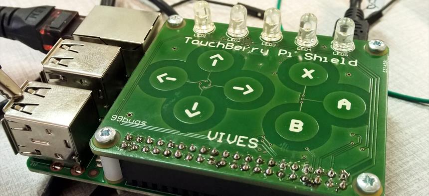
More information about the shield can be found at https://circuitmaker.com/Projects/Details/Sille-Van-Landschoot-2/TouchBerry-Pi.
When executing i2cdetect -r 1 with the TOuchBerry Pi shield attached, the output should be:
WARNING! This program can confuse your I2C bus, cause data loss and worse!
I will probe file /dev/i2c-1 using read byte commands.
I will probe address range 0x03-0x77.
Continue? [Y/n]
     0  1  2  3  4  5  6  7  8  9  a  b  c  d  e  f
00:          -- -- -- -- -- -- -- -- -- -- -- -- --
10: -- -- -- -- -- -- -- -- -- -- -- 1b -- -- -- --
20: -- -- -- -- -- -- -- -- -- -- -- -- -- -- -- --
30: -- -- -- -- -- -- -- -- -- -- -- -- -- -- -- --
40: -- -- -- -- -- -- -- -- 48 -- -- -- -- -- -- --
50: 50 -- -- -- -- -- -- -- -- -- -- -- -- -- -- --
60: 60 -- -- -- -- -- -- -- 68 -- -- -- -- -- -- --
70: -- -- -- -- -- -- -- --
2
3
4
5
6
7
8
9
10
11
12
13
Interacting with an I2C device
Wiringpi has a builin class which allows easy interaction with an I2C device. The code example below shows how to read the current pressed pad from the QT1070 touch sensor.
import wiringpi
from time import sleep

wiringpi.wiringPiSetup()    # Use WiringPi numbering

touch = wiringpi.wiringPiI2CSetup(27)   # 0x1B

# Set internal pointer to register 3 (key state)
wiringpi.wiringPiI2CWrite(touch, 3)

# Start reading the key state
while True:
  sleep(0.1)
  value = wiringpi.wiringPiI2CRead(touch)
  print("State = {}".format(value))
2
3
4
5
6
7
8
9
10
11
12
13
14
15
The LED driver is a bit more complicated to configure. The channels need to be configured in PWM mode and the oscillator needs to be enabled.
import wiringpi
from time import sleep

wiringpi.wiringPiSetup()    # Use WiringPi numbering

leds = wiringpi.wiringPiI2CSetup(0x60)   # 0x60

# Setup the device for PWM
for i in range(0,3):
  wiringpi.wiringPiI2CWriteReg8(leds, 0x14+i, 0xAA)
  sleep(0.1)

# Enable oscillator
wiringpi.wiringPiI2CWriteReg8(leds, 0x00, 0x00)
sleep(0.1)

# Set a led
FIRST_LED = 0x02
wiringpi.wiringPiI2CWriteReg8(leds, FIRST_LED+3, 0x45)
2
3
4
5
6
7
8
9
10
11
12
13
14
15
16
17
18
19
Using a library
You can imagine this code becoming quite a mess quickly. For this reason we created a nice clean library to interact with the TouchBerry Shield.
This library can be installing by issueing the following commands:
sudo apt-get update && sudo apt-get install python3-smbus
pip3 install touchberrypi
2
More information about the library can be found at its repository on GitHub at https://github.com/BioBoost/python-touchberrypi-package.
Below is a more complex example of a dynamic nightrider light which is controllable using the touch pads.
from time import sleep
import sys
from touchberrypi import TouchberryPi
from touchberrypi import Color
from touchberrypi import Colors
from touchberrypi import Led
from touchberrypi import TouchKey

shield = TouchberryPi()

colors = [Colors.RED, Colors.GREEN, Colors.CYAN, Colors.MAGENTA]

interval = 0.3
currentLed = 0
colorIndex = 0
delta = 1
partyMode = False

def on_key_down(key):
    global interval
    global colorIndex
    global partyMode

    if key == TouchKey.UP:
        interval = interval / 2.0
    elif key == TouchKey.DOWN:
        interval = interval * 2.0
    elif key == TouchKey.X:
        colorIndex = (colorIndex + 1) % len(colors)
    elif key == TouchKey.B:
        partyMode = not partyMode

shield.on_key_down(on_key_down)
shield.set_all_leds(Colors.BLACK)
shield.start_touch_listener(0.1)

while True:
    shield.set_all_leds(Colors.BLACK)
    shield.set_led(currentLed,colors[colorIndex])
    currentLed = (currentLed + delta)

    if currentLed >= 4 or currentLed <= 0:
        delta = -delta
        if partyMode:
            colorIndex = (colorIndex + 1) % len(colors)

    sleep(interval)
2
3
4
5
6
7
8
9
10
11
12
13
14
15
16
17
18
19
20
21
22
23
24
25
26
27
28
29
30
31
32
33
34
35
36
37
38
39
40
41
42
43
44
45
46
47